Robotic industrial applications
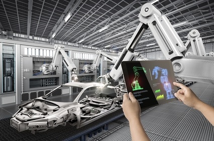
Typical robotic industrial applications are: inspection, quality control, assembling, locating parts, transporting parts and more. The vision system can be scene-related or object-related, depending on the application. In scene-related vision systems, like those developed for mapping, localization, and obstacle avoidance applications, the camera is mounted on the mobile robot. In object-related vision systems, typical of applications that handle objects, camera is mounted on the end of the robot’s arm, near the active tool.
High accuracy is required from the robotic machine vision system. Besides availing themselves of high resolution cameras, they also use (whenever possible) optical calibration. The initial calibration step consists in image distortion and deformation correction. It is usually performed with some standard target and repeated as required. For example, when temperature changes may affect the vision system. Sensor fusion is also a valid way to enhance accuracy.
Robots performing navigation tasks build a 3D model of the environment around them. When RGB cameras are used to perform the 3D modeling, objects without texture may present a challenge. Similar challenges are found with active lasers, which are sensitive to area reflections. The calibration process performs the mapping between the sensor’s 2D image and the 3D space (in real-world space).
Machine Vision systems in the industry
3D space can be reconstructed from a set of 3 RGB cameras positioned at different location and orientation, so that each point (in the 3D space) is located on all the 3 generated images.
Physical markers aid the process: they exist in the images or are projected on the scene. Feature extraction algorithm is used to detect pairable features. A classical, gradient-based algorithm or a modern deep learning classifier that was trained with features set are all valid solutions. In relatively smooth scenes (no texture or features) the projected IR pattern generates the same information. In some cases the pattern is pulsed to overcome other light sources.
Time of Flight (TOF) cameras are active cameras (as opposed to RGB cameras). They transmit a short light pulse and after that they measure the delay of the reflected pulse. In this way, the depth information is used to create a 3D image. The generated 3D scene imposes challenges to the machine vision system: noise, low resolution, inaccuracy and sensitiveness to external light. Algorithms use high rate scene re-capturing to handle such problems.
Structured light is an additional passive system. It transmits a sequence of different patterns on the environment. In this way, movements inside the environment may be detected.
Light coding, an evolution of structured light, replaces the patterns sequence. It is less sensitive to light timing accuracy, since the lights are always on.
Set of laser emitters (or scanning laser beam) generates a pattern of points. Their emitted location on the receiver shows the curvature of the surface. Machine vision is challenged by cases of surface not reflecting well: the 3D model displays holes in such locations. The algorithm uses time-sequenced laser information to fill the missing data (holes).
RSIP Vision and Machine Vision in industrial applications
RSIP Vision is experienced with 3D scene reconstruction, as well as employing machine vision algorithms to “understand” the environment. We use today mostly deep learning (CNN) classifiers for this task. Object detection as well, as described above, may be handled by the way of CNN classifiers. Contact us and we’ll tell you how.

